This project was developed as a portable auxiliary power system for campervan use, providing a practical source of 12 V, USB-C and mains AC power when camping off-grid.
The aim was to package a 120Ah LiFePO4 battery, charging hardware, power distribution and inverter into a compact, self-contained electrical cabinet while maintaining good serviceability and electrical protection.
Technical Scope
The system was built around a 120Ah LiFePO4 battery and provides:
230 V AC Power: 1000 W pure sine-wave inverter for mains-powered equipment.
USB-C Power Delivery: 65 W USB-C PD output suitable for laptop and device charging.
12 V Distribution: Multiple fused 12 V outputs, including a dedicated lighting connection.
Dual-Source Charging: AC mains charging together with DC/DC charging from the vehicle’s 12 V supply.
Electrical Protection: Main battery fuse, individually fused output circuits and a master battery isolation / emergency disconnect.
Local Controls: Front-panel switching and connections for straightforward operation in the vehicle.
Design
The design started with the physical packaging of the major components: battery, inverter, charging electronics and fuse/distribution hardware.
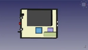
Simplified 3D models were created in FreeCAD and used to determine the minimum practical enclosure size while maintaining sufficient clearance for high-current cabling, component access and servicing. A standard 500 × 400 × 200 mm electrical cabinet provided a suitable footprint and was checked against the available installation space within the campervan.
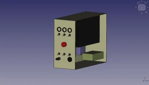
The front-panel controls and connectors were then incorporated into the CAD model to establish an ergonomic layout and check for internal mechanical interference.
Once the physical architecture was established, the complete electrical system was captured schematically in KiCad before assembly. This provided a clear reference for power distribution, protection, charging and system wiring.
Front-panel block model view demonstrating layout ergonomics.Internal view of the component spatial layout study.
Build & Implementation
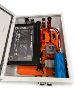
The main electrical components were mounted to the cabinet’s removable internal backplate, allowing the majority of the system to be assembled and wired outside the enclosure.
High-current battery and inverter connections were assembled using appropriately sized cable, terminals and protective devices, while lower-current loads were distributed through an individually fused blade-fuse panel. A separate high-current fuse provides primary battery protection.
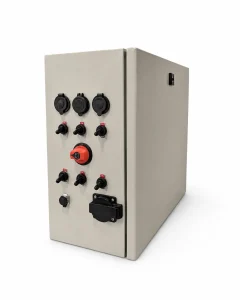
The front panel was manually drilled and assembled with the required switches, connectors and controls before final installation of the internal wiring.
The finished system was then checked for correct polarity, continuity and short circuits before the battery was connected and individual circuits were progressively commissioned.
120Ah 12V Portable Battery SystemInternal view of the completed enclosure, showcasing the final component distribution.
Testing & Qualification Stage
Initial bench testing verified the power distribution, protection and individual system outputs, including the 12 V connections, USB-C PD supply and pure sine-wave inverter.
The system has subsequently been used during several weekend camping trips, providing more representative testing under the conditions for which it was designed.
Repeated real-world use has validated the mechanical installation and electrical architecture, with the system now operating reliably as the campervan’s auxiliary power source.
Engineering Retrospective
The completed system has performed well in real-world use, but the build highlighted several areas that I would approach differently if developing a second unit or progressing the design towards small-scale manufacture.
Outsource Enclosure Machining: The manually drilled front panel was suitable for a prototype but relatively time-consuming to produce. For future builds, I would provide the completed CAD panel layout to the enclosure supplier and have the cut-outs manufactured before delivery, improving both repeatability and finish.
Improve Inverter Integration: The inverter mounting could be made more secure and better integrated with the enclosure. A future revision would use a dedicated mounting arrangement or purpose-designed enclosure, potentially incorporating flame-retardant V-0-rated 3D printed components where appropriate, while maintaining the required ventilation and thermal clearances. This would also provide an opportunity to integrate the inverter connections directly through the system panel.
Use Complete Manufacturer CAD Data: The initial enclosure model captured the primary dimensions but not the full movement of the internal locking mechanism, resulting in a minor interference with the battery during assembly. For future designs I would obtain the manufacturer’s complete CAD model before finalising the internal layout.
Design for Repeatable Manufacture: If the system progressed beyond a one-off build, I would further standardise panel machining, mounting hardware and internal wiring looms to reduce assembly time and improve consistency between units.
The project has since generated several enquiries for similar systems. A future revision would therefore be approached less as a one-off maker build and more as a product designed for repeatable low-volume manufacture.