Location: Brisbane, QLD

Edwards – Case Study – End-of-Line 3-Phase Motor Drive Automated Test System 11kVA With Regenerative Load

Professional Project
Project Type B2B Consulting
Hardware Status V3.0
Organisation Edwards Vacuum
Completion Date 2022 - Present

Problem Outline

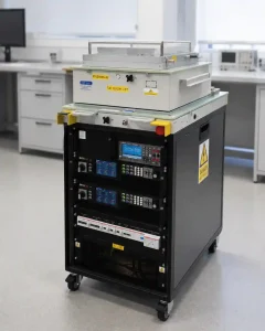
11kVA 3-phase automated motor drive test system with regenerative load.

The client required a modernised automated end-of-line test system to replace legacy equipment used to validate a range of three-phase industrial motor drives for semiconductor vacuum pumps.

The system needed to support multiple drive variants rated up to 450 V and 11 kVA, including both high- and low-voltage products, while providing a safe and repeatable production test environment. To support ongoing manufacturing requirements, the architecture also needed to be maintainable, adaptable to future product changes and capable of accepting interchangeable test fixtures.

A key requirement was the ability to test the drives under representative operating conditions. A programmable AC source provided controlled input power to the unit under test, while an 11 kVA regenerative AC load allowed energy generated during testing to be returned to the grid rather than dissipated as heat. This significantly reduced thermal loading and operating costs compared with a conventional resistive load-bank approach.
Key Technical Responsibilities

  • 3U Control Tray Design: Led the end-to-end design and engineering of the custom 3U control and instrumentation tray.
  • Mechanical Enclosure Design: Engineered and orchestrated the manufacture of a bespoke 3U 19″ sheet metal enclosure tray to securely house the control and instrumentation hardware.
  • Hardware Integration: Oversaw the physical integration of the third-party top section onto the main 19″ rack upon delivery in line with specifications.
  • System Documentation: Authored the full-system schematics, user manual, generated bills of materials, and reviewed all technical drawings.
  • Testing & Validation: Executed the final full system testing and validation prior to deployment.
  • Coordination: Liaised with technicians, project managers, and the client to ensure alignment on technical specifications and manage project delivery.


Design & Architecture

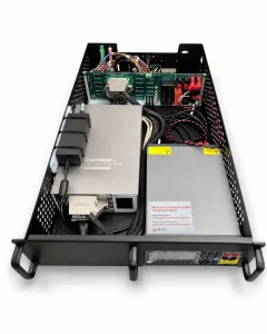
Custom 3U PXI control and instrumentation tray.

The system architecture was divided into three functional zones to improve safety, maintainability and serviceability.

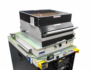
The upper section contained an interchangeable pneumatic fixture assembly used to interface with the motor drive under test. The fixture deployed test probes onto the product under pneumatic control, providing repeatable electrical connections while allowing rapid changeover between drive variants.

Below this, a custom 3U control and instrumentation tray formed the electrical core of the system, while the lower section housed the programmable AC power source, regenerative load, power distribution and high-voltage load-side hardware.

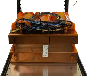
The physical scale of the system was also significant. The custom load-side transformer alone weighed approximately 170 kg, with the complete test system weighing around 380 kg, requiring the mechanical architecture, rack construction and component placement to account for substantial concentrated loads.

The control tray incorporated:

  • Custom load-side transformer — weight approximately 170 kg.

    PXI Instrumentation: Dedicated switching and measurement hardware, including an 80-channel relay matrix, 28 × 16 switching matrix and digital I/O.

  • Measurement & Communications: Precision digital multimeter together with isolated serial interfaces supporting RS-485, RS-232 and CAN communications.
  • Custom Electronics: Bespoke PCB assemblies developed for system-specific routing, interfacing and control.
  • Power Infrastructure: Dedicated AC-to-DC supplies providing 5 V, 12 V and 24 V rails together with an industrial UPS.
  • Safety Integration: Interlocked alarm and safety circuitry designed to protect the operator during automated high-voltage testing.

On the load side, a large sine-wave filter and step-down transformer conditioned the output of the motor drive before connection to the regenerative load. This reduced switching harmonics and stepped the drive output down to a voltage compatible with the load hardware.

The modular arrangement allowed product-specific fixtures to be changed without redesigning the core control, instrumentation or high-power test infrastructure.

Electromagnetic Interference (EMI) Challenges

During system validation with high-voltage drive variants, intermittent communication failures were observed within the control and instrumentation system.

Investigation identified conducted and radiated interference associated with the high-power motor-drive cabling. The original physical arrangement placed sensitive serial communication paths in close proximity to these power circuits, resulting in communication errors during operation.

Several mitigation measures were implemented:

  • Cable Rerouting: Increased physical separation between communication and high-power cabling.
  • Improved Screening: Upgraded communication cables and improved termination of cable screens.
  • Ferrite Suppression: Added ferrite components to selected power and communication paths to suppress high-frequency interference.
  • Component Relocation: Repositioned sensitive communication hardware away from high-noise areas within the enclosure.
  • Sine-Wave Filtering: Integrated load-side filtering to reduce the high-frequency switching content present at the motor-drive output.

These changes eliminated the communication instability and provided reliable operation during subsequent high-power testing.

Testing & Qualification Stage

Interchangeable pneumatic fixture for rapid, repeatable connection to multiple motor-drive variants.

System integration became one of the most demanding stages of the project. The upper fixture assembly was supplied by a third party and continued to evolve throughout development, with successive deliveries incorporating changes to components, pneumatic hardware and mechanical configuration.

Limited design documentation was initially available for this subsystem, so a significant part of the integration effort involved establishing its electrical and pneumatic operation, verifying interfaces and reconciling successive hardware revisions before complete system testing could begin.

Once the fixture hardware had been fully characterised and integrated, production motor drives were connected to the system and testing progressed using the client’s automated test software.


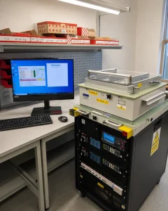
Full-system validation during automated testing.


This validation exercised the complete signal chain rather than individual subsystems: instrumentation, switching matrices, communications, safety interlocks, pneumatic actuation, high-voltage power hardware, regenerative loading, product fixtures and client software all had to operate together successfully.

A representative range of production drives was then tested across the required fixture configurations. Final system acceptance required successful automated testing of all five specified motor-drive variants, covering both high- and low-voltage products across two different fixture types.

Completion of this testing demonstrated that the system could repeatedly execute the required end-of-line production test sequence across the client’s product range.

Engineering Retrospective

Development of the test platform began in 2022 and has continued through several subsequent production builds, with further systems scheduled for delivery in 2026. The original electrical architecture remains in production use, while incremental improvements have been incorporated over successive builds to increase maintainability, reliability and ease of manufacture.

One of the defining challenges of the project was designing against a specification that continued to evolve alongside the hardware. Development timescales were frequently compressed, requiring substantial electrical, mechanical and integration work to progress in parallel while accommodating changes to fixtures, interfaces and production requirements.

With hindsight, the programme would have benefited from a more comprehensive system-level technical specification at project initiation, together with stronger configuration control and formal documentation of interface decisions. Changes in key engineering and project personnel over the lifetime of the programme also demonstrated the importance of maintaining a clear written record of technical agreements and design rationale on long-running projects.

From an engineering perspective, the modular architecture proved effective. The core control and instrumentation system has remained operational through multiple product and fixture revisions and continues to support the production test process.

Were the system being designed again today, there are areas where the architecture and implementation could be further simplified based on the experience gained. However, the ability of the original design to accommodate several years of evolving requirements provides a strong validation of the underlying system approach.

Scroll to Top